A Co2 Laser Lamp is more than a glowing tube behind a machine panel. It is a gas-based laser source that uses carbon dioxide, nitrogen, and helium inside a sealed or serviceable discharge tube. Electrical energy excites the gas mixture. Nitrogen transfers energy to carbon dioxide molecules. Those molecules release infrared light, commonly near 10.6 micrometres. Mirrors then amplify and direct the beam.
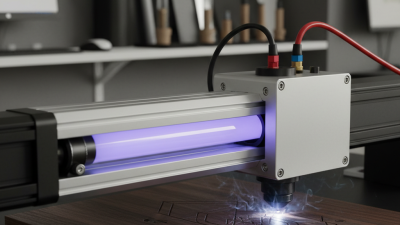
The terminology is not always clean. Some suppliers call the complete sealed tube a “laser lamp.” Others reserve that term for the excitation assembly. That distinction matters when comparing power, cooling, lifespan, and replacement cost. A Co2 Laser Lamp may support cutting, engraving, marking, medical research, or laboratory testing. Its performance depends on gas purity, optical alignment, electrode condition, and heat removal. A warm metal frame and a faint violet discharge often reveal the system’s working environment.
Market data shows why this technology remains relevant. Grand View Research estimates that the global laser technology market reached approximately USD 18.5 billion in 2023. It also forecasts continued growth through 2030. MarketsandMarkets separately identifies materials processing as a major laser application area. These reports cover wider laser categories, not every Co2 Laser Lamp. Their definitions differ, so direct comparisons require caution.
Laser pioneer Arthur Schawlow once said, “The laser is a solution looking for a problem.” His words still invite reflection. A CO2 source is powerful, but power alone does not guarantee value. Good engineering matches wavelength, beam quality, duty cycle, and safety controls to the real task. I may be simplifying one point: manufacturers measure performance differently. Readers should verify test conditions, not trust attractive headline figures.
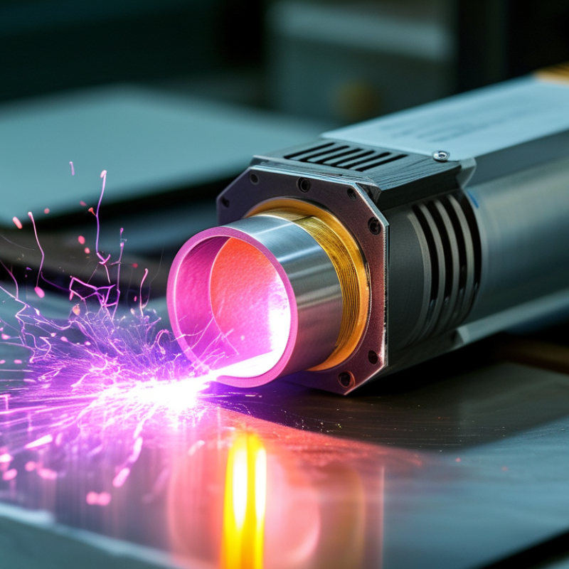
A CO₂ laser lamp is a gas-discharge laser source that produces invisible infrared light. Its most recognized output is 10.6 µm, a wavelength strongly absorbed by many organic materials. Wood, acrylic, paper, and textiles can respond quickly under focused energy. The word “lamp” can mislead, though. It does not work like an ordinary lighting bulb. Inside, an electrical discharge excites carbon dioxide molecules, while nitrogen helps transfer energy between molecular states.
The core assembly usually includes a discharge tube, gas mixture, electrodes, optical mirrors, cooling parts, and a regulated power supply. The mirrors form an optical cavity. One mirror reflects nearly all light, while the other allows a controlled beam to escape. A lens then concentrates that beam into a small, intense spot. In practical testing, alignment and cooling often matter as much as rated power. A powerful tube can still perform poorly. That point is easy to overlook.
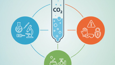
Tips: Keep the optical path clean and verify cooling flow before operation. Measure output with suitable instruments, not visual judgment. Infrared radiation is invisible, so protective controls and trained handling are essential. Gas pressure, electrode wear, and mirror condition can gradually change performance. Maintenance records help reveal these changes, although they are not perfect. Review them with actual beam measurements.
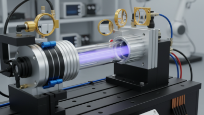
What Is a CO2 Laser Lamp and How Does It Work?
Gas-Mixture Excitation: How Electrical Discharge Creates Laser Gain
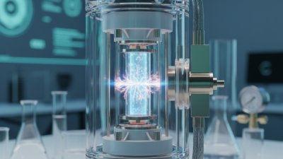
A CO2 laser lamp uses a sealed gas mixture to convert electrical energy into infrared light. The mixture commonly contains carbon dioxide, nitrogen, and helium. Small amounts of other gases may also improve stability. Inside the discharge tube, electrodes create a controlled electrical current through the gas. The glowing discharge may appear pale purple or pink.
Nitrogen plays an important supporting role. Electrical collisions excite its molecules into higher vibrational states. These states closely match an energy level in carbon dioxide. During collisions, nitrogen transfers energy to CO2 molecules, raising them to an excited vibrational state. This energy transfer creates the population inversion needed for laser gain. It is a carefully balanced process.
The excited CO2 molecules release infrared photons near 10.6 micrometers. Two aligned mirrors form an optical resonator, causing selected photons to travel repeatedly through the gas. Stimulated emission then strengthens the beam. Helium helps remove energy from lower CO2 levels and carries heat toward the tube walls. Without effective cooling, output power and tube life can decline.
The picture is not perfectly simple. Gas pressure, electrode condition, discharge uniformity, and mirror alignment all affect performance. A faintly uneven glow may indicate instability, although appearance alone cannot confirm a fault. Measuring current, temperature, and optical output gives more reliable evidence. Even a well-designed tube wastes considerable energy as heat, so ventilation and electrical protection remain essential.
A CO2 laser lamp uses an electrical discharge to energize a gas mixture inside a sealed tube. The mixture commonly includes carbon dioxide, nitrogen, and helium. Electrical energy excites nitrogen molecules first. Collisions then transfer energy to carbon dioxide molecules. This creates population inversion, where more molecules occupy an excited state than a lower one.
The real work begins inside the optical resonator. Two mirrors face each other at opposite ends of the tube. One mirror reflects nearly all infrared light. The other reflects most light but allows a controlled portion to escape. A photon moving along the tube stimulates excited CO2 molecules. Each interaction produces another photon with matching direction, phase, and wavelength. The beam grows through repeated passes.
Alignment matters more than many simple diagrams suggest. A tiny mirror tilt can weaken the beam or stop lasing completely. The gas pressure, electrode condition, and mirror cleanliness also influence stability. Small details matter. The resonator does not create energy; it organizes existing optical gain. That explanation is useful, but still incomplete. Heat, vibration, and imperfect surfaces introduce losses. In practice, engineers balance gain against these losses until one narrow beam leaves the output mirror.
What Is a CO2 Laser Lamp and How Does It Work?
A CO2 laser lamp produces infrared light, usually near 10.6 micrometres. The discharge excites carbon dioxide, nitrogen, and helium inside a sealed or flowing gas tube. In a 10 W sealed tube, mirrors and electrodes remain compact, making the source suitable for engraving, marking, and thin-material cutting. According to the 2024 MarketsandMarkets laser technology report, industrial laser demand continues to expand, driven by automation and precision processing.
Beam delivery becomes more demanding as power rises. A gold-coated or protected metal mirror redirects the infrared beam, while zinc selenide optics focus it onto the workpiece. At multi-kilowatt levels, small absorption losses create serious thermal distortion. Water cooling, clean purge gas, and stable optical mounts become essential. A 2023 industrial laser market review by Optech Consulting estimated that high-power processing systems represent a major share of industrial laser revenues, reflecting this shift toward automated cutting and welding.
Power is not the only specification. Beam quality, divergence, spot size, and cutting speed must be measured together. A 10 W sealed tube may offer simple maintenance, but its beam can degrade with age and thermal cycling. A multi-kW resonator offers greater throughput, yet alignment errors become expensive quickly. In practice, delivery is rarely perfect. Dust, vibration, and lens contamination quietly reduce performance. ISO 11145 defines important laser beam terminology, but real production testing still matters more than a catalogue number. A stronger tube does not automatically produce cleaner edges.
| Typical Output Power | Common Source Architecture | Typical Operating Wavelength | Beam Delivery Method | Cooling Approach | Typical Wall-Plug Efficiency | Typical Applications |
|---|---|---|---|---|---|---|
| 10–30 W | Sealed, low-pressure glass discharge tube with internal electrodes and a fixed gas mixture. | Usually 10.6 μm; some systems operate near 9.3 μm. | Free-space delivery using metallic mirrors, commonly with a focusing lens at the work surface. | Air cooling or passive heat sinking. | Approximately 5–12% | Marking, engraving, thin nonmetal cutting, laboratory demonstrations, and small-format processing. |
| 30–150 W | Sealed or internally water-cooled RF-excited tube; RF excitation can provide a compact, stable discharge. | Primarily 10.6 μm. | Folded free-space optical path with copper or molybdenum mirrors and a ZnSe focusing optic. | Forced air or liquid cooling, depending on duty cycle and tube construction. | Approximately 8–15% | Sign cutting, packaging, textiles, plastics, wood, acrylic, rubber, and general engraving. |
| 150–500 W | Diffusion-cooled slab, transverse-flow, or sealed industrial resonator designed for continuous operation. | 10.6 μm is standard; shorter-wavelength variants may be selected for particular material responses. | Free-space beam path with enclosed articulated arms, beam expanders, steering mirrors, and a ZnSe focusing assembly. | Closed-loop liquid cooling is commonly used. | Approximately 10–18% | High-speed cutting of nonmetals, plastics, wood, composites, stone, and industrial marking. |
| 500 W–1 kW | Sealed slab or fast-axial-flow resonator with higher discharge volume and active gas-temperature control. | Typically 10.6 μm. | Enclosed free-space delivery; beam expanders and reflective optics are selected to control divergence and spot size. | Chilled-water circulation for the resonator, optics, and power electronics. | Approximately 12–20% | Industrial cutting, welding of selected materials, large-area engraving, and high-throughput fabrication. |
| 1–3 kW | Fast-axial-flow or transverse-flow gas laser with continuous gas circulation, heat exchangers, and gas replenishment. | Usually 10.6 μm. | Protected free-space beam delivery through sealed tubes or articulated beam-guidance systems; process heads often include assist-gas nozzles. | Industrial closed-loop water cooling with heat-exchanger capacity matched to waste heat. | Approximately 15–22% | Thick polymer and composite cutting, large-format processing, surface treatment, and specialized welding. |
| 3–6 kW | Large fast-flow or transverse-flow resonator using controlled gas circulation and high-capacity discharge power supplies. | Commonly 10.6 μm. | Rigid enclosed free-space delivery with multiple steering mirrors, beam monitoring, and a dedicated processing head. | High-capacity recirculating water chiller; separate thermal management may be required for the power supply. | Approximately 15–25% | Heavy-gauge nonmetal cutting, large composite structures, industrial surface processing, and specialized manufacturing. |
| Above 6 kW | Multi-module fast-flow or transverse-flow architecture, often combining several resonator sections or beam paths. | Generally 10.6 μm, with wavelength selected according to absorption, optics, and process requirements. | Engineered free-space beam combining or individually routed beams, using protected optics, beam diagnostics, and automated alignment control. | Dedicated high-flow liquid cooling for resonators, mirrors, beam-combining optics, and electronics. | Approximately 15–25%, depending on architecture and operating point. | Very high-throughput cutting and processing of thick nonmetallic materials, large composite components, and specialized industrial systems. |
A CO2 laser lamp is a gas-discharge tube that converts electrical energy into infrared laser light. Its gas mixture usually contains carbon dioxide, nitrogen, and helium. An electrical field excites the gas, while mirrors guide and amplify the light inside the tube. The useful output is often only 10–20% of the electrical input. The rest becomes heat. That figure is practical, not perfect. Tube design, power level, gas pressure, and alignment can shift it noticeably.
Cooling controls both performance and safety. Water-cooled tubes need steady flow through a clean circuit. The coolant should remain within the manufacturer’s specified temperature range, often near room temperature. A small pump, blocked channel, or warm workshop can raise tube temperature quickly. Heat may cause unstable output, cracked seals, or shortened service life. Keep the radiator clear. Watch the return temperature.
Service life depends heavily on operating habits. Frequent operation near maximum power stresses the gas mixture and electrode surfaces. Gentle warm-up, correct current, and regular optical inspection usually help. Many tubes last from roughly 1,000 to 10,000 hours, but this range is not a promise. Service records matter more than a brochure estimate. A fading beam, difficult ignition, or rising current can signal wear. I would not treat every output drop as tube failure; dirty optics and weak cooling can look surprisingly similar.